One of the first things I learned in school about using load combinations was that you had to pick eitherLoad and Resistance Factor Design(LRFD)/Strength Design(SD) orAllowable Stress Design(ASD) for a building and stick with it, no mixing allowed! This worked for the most part since many material design standards were available in a dual format. So even though I may prefer to use LRFD for steel and ASD for wood, when a steel beam was needed at the bottom of a wood-framed building that was designed using ASD load combinations, the steel beam could easily be designed using the ASD loads that were already calculated for the wood framing above since AISC 360 is a dual- format material standard. And when the wood-framed building had to anchor to concrete, ASD anchor values were available in the IBC for cast-in-place anchors and from manufacturers for post-installed anchors in easy-to-use tables, even though ACI 318 was not a dual-format material standard. (Those were good times!)

Then along came ACI 318-02 and its introduction ofAppendix D – Anchoring to Concrete, which requires the use of Strength Design. The 2003 IBC referenced Appendix D for Strength Design anchorage, but it also provided a table of ASD values for some cast-in-place headed anchors that did not resist earthquake loads or effects. This option to use ASD anchors for limited cases remained in the 2006, 2009 and 2012 codes. In the 2015 IBC, all references to the ASD anchor values have been removed, closing the book on the old way of designing anchors.
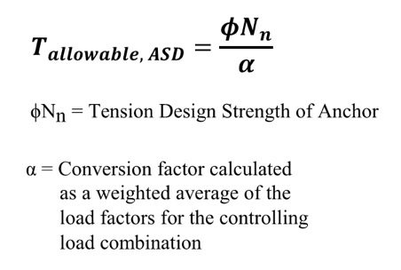
ICC-ES-equation-tensionSo what do you do now? Well, there is some guidance provided by ICC-ES for manufacturers to convert calculated SD capacities to ASD allowable load values. Since there is no conversion procedure stated in the IBC or referenced standards, designers may want to use this generally accepted method for converting anchor capacities designed using ACI 318. ICC-ES acceptance criteria for post-installed mechanical and adhesive anchors (AC193 and AC308) and cast-in-place steel connectors and proprietary bolts (AC398 and AC399) outline a procedure to convert LRFD capacities to ASD using a weighted average for the governing LRFD/SD load combination. So if the governing load combination for this anchor was 1.2D + 1.6L and the dead load was 1,000 pounds and the live load was 4,000, then the conversion factor would be (1.2)(0.2) + (1.6)(0.8) = 1.52 (keep in mind that the LRFD/SD capacity isdividedby the conversion factor in the ICC-ES equation shown here for tension).

Right away, there are a few things that you may be thinking:

  1. What about load factors that may exist in ASD load combinations?
  2. It may just be easier to just recalculate my design loads using LRFD/SD combinations!
  3. The resulting allowable loads will vary based on the load type, or combination thereof.
  4. If the ACI 318 design strength is limited by the steel anchor, then the conversion will result in an allowable load that is different from the allowable load listed for the steel element in AISC 360.

Let's take a look at these objections one by one.

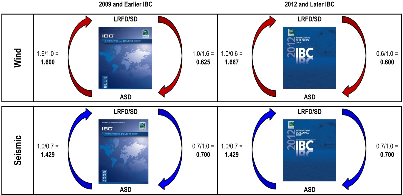
Item 1: Since unfactored earthquake loads are determined at the ultimate level in the IBC, they have an LRFD/SD load factor of 1.0 and an ASD load factor less than 1.0, which is also true for wind loads in the 2012 and 2015 IBC (see graphic below). Using the LRFD/SD load factor of 1.0 obviously does not convert the capacity from LRFD to ASD so you must also account for ASD load factors when calculating the conversion factor. To do so, instead of just using the LRFD load factor, use the ratio of LRFD Factor over ASD Factor. So if the governing load combination for an anchor was 0.9D + 1.0E and the dead load was 1,000 pounds and the seismic load was 4,000, then the conversion factor would be (0.9)(0.2) + (1.0/0.7)(0.8) = 1.32.
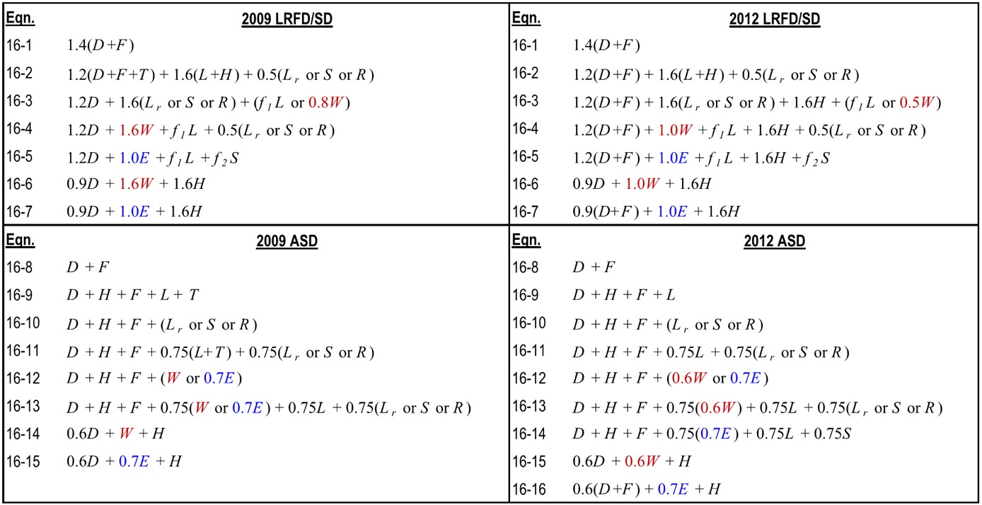
ICC-ES-equations

Item 2: Even though the weighted average conversion requires you to go back and dissect the demand load into its various load types, often this can be simplified. ICC-ES acceptance criteria permit you to conservatively use the largest load factor. The most common application I run into is working with ASD-level tension loads for wood shearwall overturning that must be evaluated using SD-level capacities for the concrete anchorage. Since these loads almost always consist of wind or seismic loads, using the largest factor is not overly conservative. Depending on the direction in which you are converting the demand loads or resistance capacities, the adjustment factors are as shown in the figure below. Affected bob体育欧洲杯哪里可以买球 products now have different allowable load tables for each load type. (For examples, see pp. 33-36 of ourWood Construction Connectorscatalogfor wind/seismic tables and pp. 28-30 of ourAnchoring and Fastening Systemscatalogfor static/wind/seismic tables.)
IBC-ealier-later

Item 3: I am unsure whether there is any sound rationale for having allowable loads for an anchor resisting 10% dead load and 90% live load differ from those of an anchor that resists 20% dead load and 80% live load. Perhaps a reader could share some insight, but I just accept it as an expedience for constructing an ASD conversion method for a material design standard that was developed for SD methodology only.

Item 4: We have differing opinions within our engineering department on how to handle the steel strength component of the various SD failure modes listed in ACI 318. Some believe all SD failure modes in ACI 318 should be converted using the load factor conversion method. I side with others who believe that the ASD capacity of a steel element should be determined using AISC 360. So when converting SD anchor tension values for a headed anchor, I would apply the conversion factor to the concrete breakout and pullout failure modes from ACI 318, but use the ASD steel strength from AISC 360.

Finally, I wanted to point out that the seismic provisions in ACI 318, such as ductility and stretch length, must be considered when designing anchors and are not always apparent when simply converting to ASD. For this reason, I usually suggest converting ASD demand loads to SD levels so you can use ourAnchor Designer™software to check all of the ACI 318 provisions. But for some quick references, we now publish tabulated ASD values for our code-listed mechanical and adhesive anchors in ourC-A-2016catalog — just be sure to read all of the footnotes!
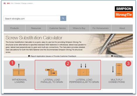
At bob体育欧洲杯哪里可以买球 , we do our best to offer tools that make your job easier. One such tool is the Screw Substitution Calculator. It's a quick and easy-to-use web app created to help you calculate and design using bob体育欧洲杯哪里可以买球 fasteners. The app can be used in two ways: (1) to design for a given load and (2) to provide a substitution for NDS fasteners. The app covers design for withdrawal loading, lateral loading and multi-ply connections.For each of these applications you can either design for a load or input the specified NDS fasteners and design an alternate bob体育欧洲杯哪里可以买球 screw substitution. The app can generate detailed calculations in a PDF format for any of the selections made, and these calculations can be used for submittals.

Note that although the tool currently does not address corrosion issues, corrosion resistance should be an important consideration before selecting screws for your application.

Below is a screenshot of theScrew Substitution Calculator. As explained above, the app can design for

  1. Withdrawal Loading
  2. Lateral Loading
  3. Multi-Ply Connections

screw-substitution-calculator-main

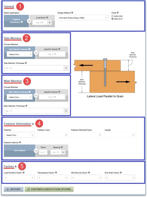
The input sections forWithdrawal LoadingandLateral Loading(parallel or perpendicular to grain) are similar. A screenshot ofLateral Load Parallel to Grainis shown below.

screw-substitution-calculator-overview

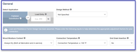
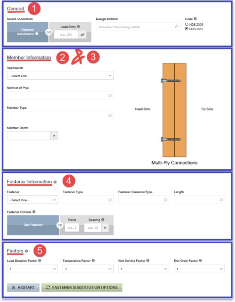
Step 1: General Information In this section, you are requested to select eitherFastener Substitutionor aLoad Entry. If you choose fastener substitution, the app will request in step 4,Fastener Information, that you enter the original fastener design. The fastener substitution calculator will provide bob体育欧洲杯哪里可以买球 fastener alternatives for the NDS fasteners. The NDS fasteners covered in this app are bolts, lag screws, wood screws and nails.

If you chooseLoad Entry, you will notice that theFastener Informationstep will disappear and no longer be available for input. Next, select a category from the Design Method section. Available options areAllowable Stress Design (ASD), Load and Resistance Factor Design (LRFD)andNot Specified, if you are not sure of the design method. If theNot Specifiedoption is selected, the design assumes theLoad and Resistance Factor Designmethod, and it further prompts you to answer a few more questions related toWood Moisture Content, Connection TemperatureandEnd Grain Insertion.

screw-substitution-calculator-general

Step 2: Side Member –In this section, all the information regarding the side member is entered. You can either select a species from the drop-down list or enter the specific gravity of the member manually in the text box. The information button lists all the available specific gravities for wood species combinations from NDS. Then enter the (actual, not nominal) thickness of the side member.

Step 3: Main Member –Similar to step 2, enter all information regarding the main member.

Step 4: Fastener Information –If theFastener Substitutionoption is selected in step 1, step 4 will require you to enter information about the NDS fasteners used in the initial design. Enter the fastener type (bolt, lag screw, screw or nail), along with its diameter and length. From the fastener option list you can either select one fastener substitute at a time for each NDS fastener or enter the number of rows and the spacing of NDS-designed fasteners to determine bob体育欧洲杯哪里可以买球 fastener options and their spacing requirements.

Step 5: Factors –Enter all factors required for designing the connection. Information pertaining to each factor is provided by clicking the information (i) button. You can use this as a guide for entering the factors.

Once all the input is entered, click on theFASTENER SUBSTITUTION OPTIONSbutton.

screw-substitution-calculator-options

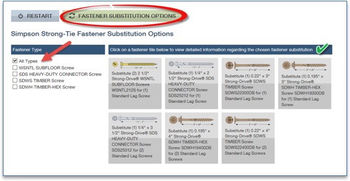
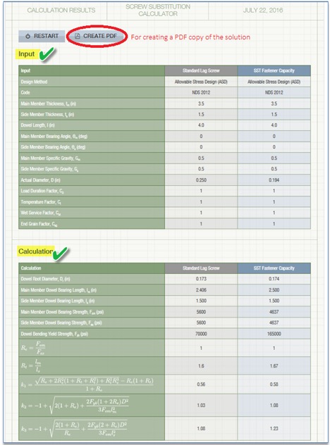
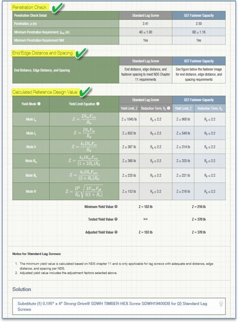
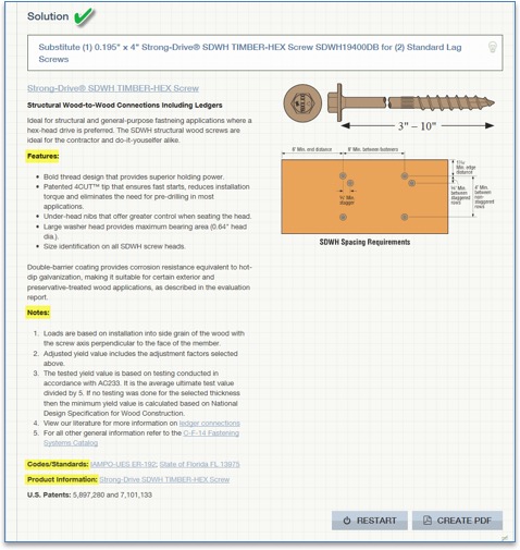
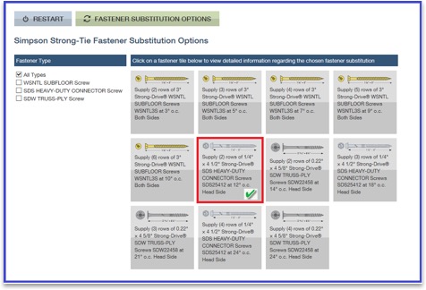
ClickingFASTENER SUBSTITUTION OPTIONSreveals the available solutions. As a default, theAll Typesbox is checked underFastener Type, as shown above. You can refine the solutions by unchecking this box and selecting any of the specific fasteners listed – SDWH TIMBER-HEX Screw solutions, for example. On the right, the available solutions are displayed for selection. When a selection is made, the app displays all the input and output for that solution as shown in the screenshot below. You can also create a PDF copy for any of the solutions by clicking onCREATE PDFbutton.

screw-substitution-calculator-create-pdf

screw-substitution-calculator-create-pdf-2

screw-substitution-calculator-solution

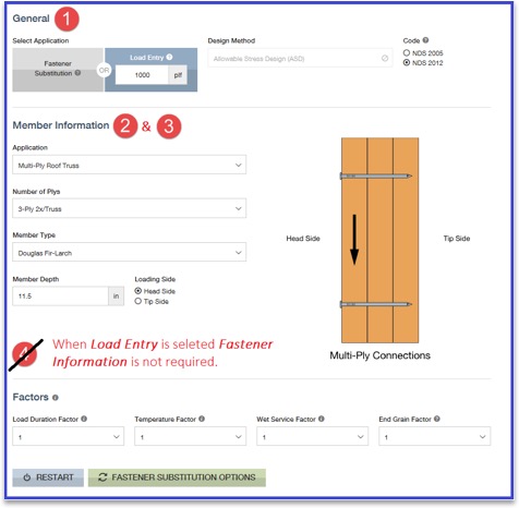
ForMulti-Ply Connections, the input for side members and main members is combined intoMember Informationas shown in the screenshot below. Once the input is entered, click theFASTENER SUBSTITUTION OPTIONSbutton to display results. Similar to withdrawal loading or lateral loading, you can create aPDF copyof the calculations.

screw-substitution-calculator-steps

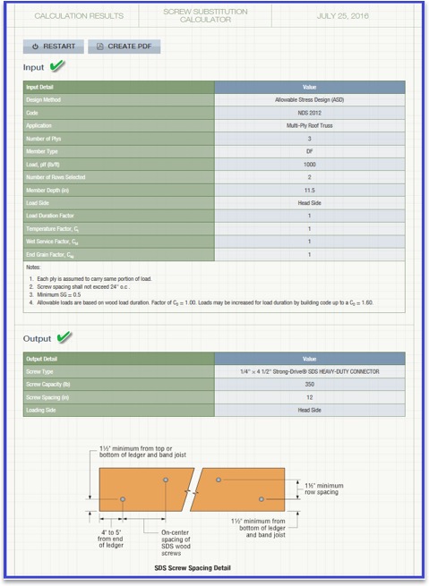
Let's design a 3-ply connection with (3) 2 x 12 DF members for a load of 1,000 plf.

screw-substitution-calculator-steps-2

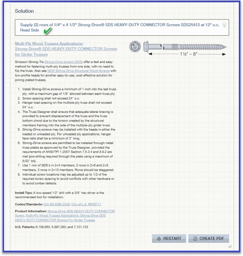
By clickingFASTENER SUBSTITUTION OPTIONS, you can see all the available bob体育欧洲杯哪里可以买球 fastener solutions. You can then select any of the options to generate detailed output. A screenshot of the output, solution and information regarding the selected fastener is displayed below. You can create a PDF copy of the solution by clicking theCREATE PDFbutton.

screw-substitution-calculator-selection

screw-substitution-calculator-output

screw-substitution-calculator-output-2

Now that you know how easy it is to design using ourScrew Substitution Calculator, you can start using this tool for your future projects. We welcome your feedback on the features you find useful as well as on how we could make this program better suit your needs. Let us know in the comments below.

This week's post was written by Bob Leichti, Manager of Engineering for Fastening Systems. Prior to joining bob体育欧洲杯哪里可以买球 in 2012, Bob was an Engineering Manager covering structural fasteners, hand tools, regulatory compliance and code reports for a major manufacturer of power tools and equipment. Prior to that, Bob was a Professor in theDepartment of Wood Science and EngineeringatOregon State University. He received his B.S. and M.S. from theUniversity of Illinois, and his M.S. and Ph.D. fromAuburn University.

Structures and connections can be designed either using Allowable Strength Design (ASD) method or Load and Resistance Factor Design (LRFD) method. In the ASD method, the allowable strength is calculated by dividing the nominal strength by a safety factor. In the LRFD method, the design strength is calculated by multiplying the nominal strength by the resistance factor. In design, the adjusted ASD design value is compared to a calculated load or stress. As long as the adjusted ASD design value exceeds the calculated load of stress, then the ASD design value is judged safe. In LRFD design, the nominal strength is equated to factored loads. If the factored strength is greater than the factored loads, then the design can be accepted. ASD is the more common method adopted in the professional world.

LRFD is relatively new to wood design. Prior to 2005, the National Design Specification for Wood Construction (NDS) was based on allowable stress design (ASD). In the 2005 edition, the American Wood Council incorporated Load and Resistance Factor Design (LRFD) into the NDS. To this day, most wood design in the US relies on ASD, but the use of LRFD is becoming more common. On the other hand, the steel design industry already uses the LRFD philosophy for design, and for that reason, design values for steel self-drilling tapping screws are offered in both ASD and LRFD.

The published design values for bob体育欧洲杯哪里可以买球 wood fastener products are in ASD format and the allowable loads are generally shown at a load duration factor of CD= 1.0. The reference design loads listed shall be multiplied by all adjustment factors listed in Table 10.3.1 of NDS 2012 to determine adjusted design values. The load tables are listed in ASD format because ICC-ES acceptance criteria, such as AC233 (Alternate Dowel-type Threaded Fasteners) and AC120 (Wood Frame Horizontal Diaphragms, Vertical Shear Walls, and Braced Walls with Alternate Fasteners), that are used to qualify structural wood screws do not address the development of LRFD values for wood screws. However, one can establish the nominal strength values for fasteners from reference ASD design values for use in LRFD format by following the instructions of NDS (2012), Table 10.3.1. Reference design values shall be multiplied by the format conversion factor KFas specified in Table N1 of NDS 2012. Format conversion factors adjust reference ASD design values to LRFD reference resistances. They are also multiplied by the resistance factor, Φ as specified in Table N2 and Time Effect Factor, λ as specified in Table N3.

For e.g., the table below lists the ASD allowable shear loads for SDWS screw in Douglas Fir-Larch and Southern Pine Lumber:

SDWS ­ Allowable Shear Loads ­ Douglas Fir-Larch and Southern Pine Lumber
Strong-Drive SDWS TIMBER-Screw Allowable Shear Loads Douglas Fir-Larch and Southern Pine Lumber

For the SDWS22300DB screw with a wood side member thickness of 1.5 inches, the allowable shear load is 255 lbs. with a wood load duration factor of CD= 1.0. To convert this to an LRFD load, refer to table 10.3.1 of NDS 2012 and Appendix N, Tables N1, N2 and N3. Per Table 10.3.1 we need to multiply the reference load with format conversion factor KF, resistance factor, Φ and time effect factor, λ From the Table N1, the format conversion factor KF for connections is 2.16/Φ. From Table N2, for connections Φ=0.65. Let us assume a λ of 1.0 from Table N3. The LRFD load is calculated by multiplying the allowable shear load with the factors above.

LRFD load=Allowable shear load (at a load duration factor of CD= 1.0)xKF xΦxλ

LRFD Load=255x(2.16/0.65)x0.65x1.0=551 lbs.

For steel self-drilling, self-tapping screws, the omega and resistance factors used for calculating ASD and LRFD loads are based on American Iron and Steel Institute (AISI) standard S100. For bob体育欧洲杯哪里可以买球 steel self-drilling, self-tapping screws the load tables are listed in both ASD and LRFD format.

If the screw connection capacities are calculated based on tests, the ASD values are calculated by dividing the tested nominal strength which is the average of the ultimate strength values from all the tests with the safety factor, Ω. For LRFD load, the tested nominal strength is multiplied by a resistance factor, Φ. When tests are performed for evaluating the connection capacities, the safety factor, Ω and the resistance factor, Φ are evaluated in accordance with Section F of AISI S100. bob体育欧洲杯哪里可以买球 derives the LRFD values for steel self-drilling, self-tapping screws in LRFD format because this is part of ICC-ES AC118 (Tapping Screw Fasteners). See evaluation reportICC-ES ESR 3006for examples of ASD and LRFD design values for the same fastener products.

If the screw capacities are determined based on the calculated nominal strength, the ASD loads and LRFD loads are determined based on Section E4 of AISI S100. For e.g., the table below lists the ASD loads and the LRFD loads based on calculations for #14 x 1" screw.

E ­ Cold-Formed Steel Member Connection Loads, Steel to Steel
E Cold-Formed Steel Member Connection Loads, Steel to Steel

From the table, for 33 mil (20ga) steel to 33 mil (20ga) steel shear connection, the calculated nominal shear strength is 600 lbs.

Nominal Strength = 600 lbs.

From Section E4, the safety and resistance factors for connections are:

Ω= 3.0

Φ= 0.5

ASD Load = Nominal Strength/Ω = 600 lbs./3.0 = 200 lbs.

LRFD Load = Nominal Strength xΦ = 600 lbs.x 0.5 = 300 lbs.

Now that you know the basics of ASD and LRFD, make sure you choose the one best suited for your specific material and construction application. If you have ideas for which of our products you would like to see in ASD and LRFD loads, be sure to let us know!

In April's post about theOmega Factor, one commenter asked of the 1.2 increase allowed by ASCE 12.4.3.3,"Why do they allow a stress increase for allowable combinations? Seems unconservative for steel now that they have essentially balanced the ASD capacity with LRFD."

To be honest, I have never spent much time analyzing which design methodology was more or less conservative. If I was designing with wood I would use ASD, and if it was with concrete I would use LRFD. Steel was strictly ASD early on in my design career, but LRFD usage grew. The question about balance made me curious. Are the load combinations balanced?

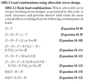
2009 IBC Basic ASD Load Combinations
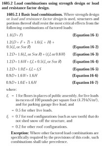
2009 IBC LRFD Load Combinations

Of course, just comparing the load combinations would be meaningless. We know the LRFD combinations result in higher design forces. But those higher forces are compared to higher design strengths. So we need to normalize things.

Continue Reading